Hello all,
I recently ordered a couple of STM32F103C6T6. This is my first project with the STM32. I have been using Arduino and ESP8266 until now.
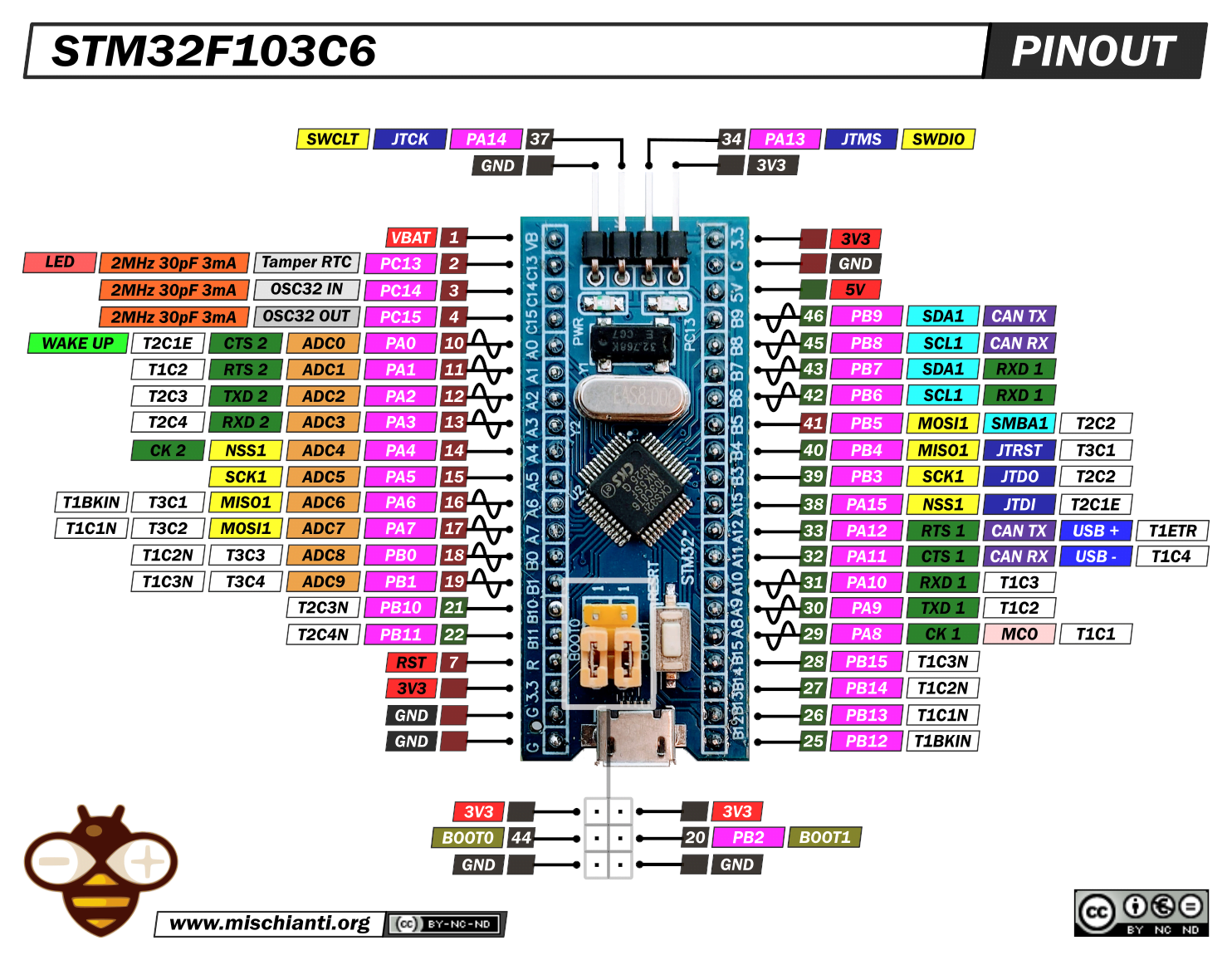
While creating my schematic, I noticed there are 3 pins labeled as RXD1: https://www.mischianti.org/wp-content/u ... lution.png
So how does this worm? I assume TX1 and RX1 are used for USB serial. Does that mean I can't use any of the 3 pins labeled RX1? Or can I use 2 out of 3 for general io?
Thanks in advance!
Multiple UART1 pins?
Re: Multiple UART1 pins?
read under AFIO in the datasheet.
Basically some of the peripherals pins show up on physical pins by default, or through remapping (either partial or full). Thus what you see.
Basically some of the peripherals pins show up on physical pins by default, or through remapping (either partial or full). Thus what you see.
Re: Multiple UART1 pins?
Thanks. I found in the datasheet that PA9 and PA10 TX1 and RX1 fall under "alternate function" and PB6 and PB7 fall under "remapped".
I don't understand the difference completely, but can I assume that normally, PA9 and PA10 will be used for serial and PB6 and PB7 are free to use as gpio? Unless I specify (remap?) the PB6 and PB7 pins, then it's the other way around?
PS. Apparently there is a typo in the pinout I attached. PB6 is TX1 according to the datasheet. Not RX1.
-
mrburnette
- Posts: 633
- Joined: Thu Dec 19, 2019 1:23 am
Re: Multiple UART1 pins?
Most common microcontrollers have more capabilities than can be utilized at one time because the physical standard sizes limit the number of physical pins. Chip architects and engineer decide how the default "pins" will be configured. Internal switching then manages how defaults can be overridden.I don't understand the difference completely,
- Pinouts.jpg (61.45 KiB) Viewed 8081 times
- Attachments
-
- Pinouts.jpg (61.45 KiB) Viewed 8081 times
Re: Multiple UART1 pins?
To make life simplier, just consider the "alternate functions", you can either *configure* them as gpio or alternate function but not both at the same time.Istria wrote: Sun Jun 05, 2022 10:06 pm Thanks. I found in the datasheet that PA9 and PA10 TX1 and RX1 fall under "alternate function" and PB6 and PB7 fall under "remapped".
I don't understand the difference completely, but can I assume that normally, PA9 and PA10 will be used for serial and PB6 and PB7 are free to use as gpio? Unless I specify (remap?) the PB6 and PB7 pins, then it's the other way around?
PS. Apparently there is a typo in the pinout I attached. PB6 is TX1 according to the datasheet. Not RX1.
if in the special case that you used an alternate function at a set of pins, but you still need the other alternate functions at the same pin, then take a look at remapped to see if you can still have them (the alternate function). more often, you could find the same alternate functions at other pins instead of using remapped.
on stm32, pretty much 'all' pins can be configured as gpio, except for a some that can't. functions such as uart is at the pins documented as 'alternate functions' and only if you configure them.
to use an alternate function e.g. uart. there are 2 sets of tasks
1) enable and configure that alternate function
2) configure the pins and select alternate function instead of gpio
miss out one any 1 of the steps and you won't see the alternate function at the pin. it will generally just be gpio.
this includes even things like adc which is an alternate function. most of these are 'hidden' away in the *dunio api and you configure that pin using
Code: Select all
pinMode(pin, MODE_SELECT_PARAM);